
Highlight
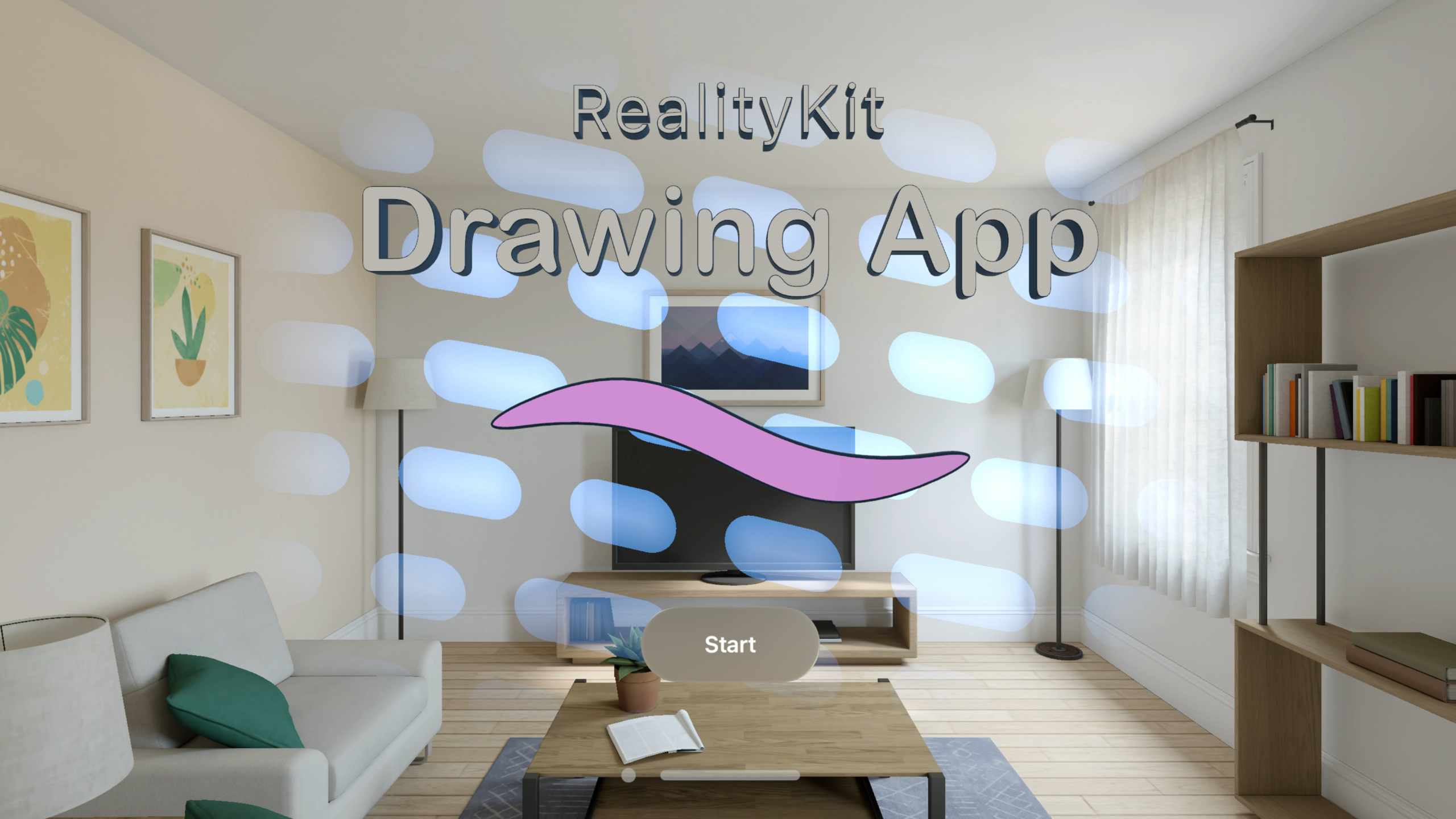
本セッションは空間描画アプリの構築を通じて、visionOS 2.0 の RealityKit 新機能を体系的に紹介します。アプリでは指のピンチで空間に描画でき、ソリッドブラシとスパークルブラシの 2 種類、色と太さの調整に対応しています。
主要内容
visionOS で空間描画アプリを作る最初のステップは、指の位置を取得することです。visionOS 1.0 では ARKit 経由で間接的にハンドアンカーデータを取得する必要があり、手順が煩雑で、ARKit session と RealityKit の Immersive Space は独立した 2 つのシステムでした。visionOS 2.0 では SpatialTrackingSession が導入され、RealityKit レイヤーで直接トラッキング権限をリクエスト。AnchorEntity の transform が自動的に手のポーズを更新し、コード量が減り、ロジックも明確になります。
手のデータを取得したら、ユーザーの筆跡をリアルタイムで 3D ジオメトリとしてレンダリングする必要があります。従来の RealityKit MeshResource は連続メモリレイアウト——すべての頂点位置をまとめ、すべての法線をまとめる——新しい頂点を追加するたびに大量のデータ移動が発生します。毎フレーム成長するストロークメッシュでは、このレイアウトがパフォーマンスのボトルネックです。visionOS 2.0 の新しい LowLevelMesh API では頂点バッファレイアウトをカスタマイズでき、インターリーブ配置、複数バッファ、triangle strip トポロジーに対応し、Metal compute shader から直接頂点データを書き込むことも可能です。既存の GPU ジオメトリ処理パイプラインをゼロコピーで RealityKit に接続できます。新しい LowLevelTexture API と組み合わせ、描画アプリ全体のメッシュ生成とテクスチャ更新を GPU で処理し、フレームレートを確保できます。
詳細
SpatialTrackingSession:ARKit に代わるトラッキング入口
ImmersiveSpace では AnchorEntity を手の関節にアンカーできます。しかし AnchorEntity の transform を実際に更新するには、トラッキング権限のリクエストが必要です。SpatialTrackingSession は visionOS 2.0 の新 API です(04:18):
// Retain the SpatialTrackingSession while your app needs access

let session = SpatialTrackingSession()

// Declare needed tracking capabilities
let configuration = SpatialTrackingSession.Configuration(tracking: [.hand])

// Request authorization for spatial tracking
let unapprovedCapabilities = await session.run(configuration)

if let unapprovedCapabilities, unapprovedCapabilities.anchor.contains(.hand) {
    // User has rejected hand data for your app.
    // AnchorEntities will continue to remain anchored and update visually
    // However, AnchorEntity.transform will not receive updates
} else {
    // User has approved hand data for your app.
    // AnchorEntity.transform will report hand anchor pose
}
キーポイント:
SpatialTrackingSession()でセッションインスタンスを作成——トラッキングが必要な間は参照を保持Configuration(tracking: [.hand])でハンドトラッキング能力を宣言session.run(configuration)でシステムの権限ダイアログを表示し、未承認の能力リストを返す- 権限拒否時、AnchorEntity は視覚的には更新されるが transform はデータを受け取らない——戻り値を確認してグレースフルデグラデーション
- SpatialTrackingSession 使用後、AnchorEntity は RealityKit 物理システムとも連携可能
MeshResource extruding:2D パスを 3D モデルに押し出し
アプリのキャンバス縁は SwiftUI Path で 2 つの同心円を定義し、3D に押し出します(07:07):
let path = SwiftUI.Path { path in
    path.addArc(center: .zero, radius: outerRadius,
        startAngle: .degrees(0), endAngle: .degrees(360),
        clockwise: true)
    path.addArc(center: .zero, radius: innerRadius,
        startAngle: .degrees(0), endAngle: .degrees(360),
        clockwise: true)
}.normalized(eoFill: true)
var options = MeshResource.ShapeExtrusionOptions()
options.boundaryResolution
    = .uniformSegmentsPerSpan(segmentCount: 64)
options.extrusionMethod = .linear(depth: extrusionDepth)

return try MeshResource(extruding: path,
                        extrusionOptions: extrusionOptions)
キーポイント:
normalized(eoFill: true)で even-odd 塗りつぶしルールを有効化——2 つの同心円の間がリング領域になるboundaryResolutionで弧の細分化精度を制御——64 セグメントでリングは十分滑らかextrusionMethod = .linear(depth:)で Z 軸方向に指定深度で押し出し- 同じ API で AttributedString の 3D テキスト押し出しにも対応(27:01)。面ごとの material index とベベル半径を指定可能
注意:visionOS の foveated rendering では、細く高コントラストのエッジにちらつきが生じることがあります。セッションでは visionOS シーンで細線ジオメトリを避け、エッジを厚くして視覚的アーティファクトを除去することを明示的に推奨しています。
HoverEffectComponent:新しいハイライトとシェーダーのホバー効果
visionOS 2.0 では HoverEffectComponent に 2 つの新しいホバー効果が追加(09:33):
let hover = HoverEffectComponent(
    .highlight(.init(
        color: UIColor(/* ... */),
        strength: 5.0)
    )
)
placementEntity.components.set(hover)
キーポイント:
.highlightで entity に均一なハイライト色を適用;strengthで鮮やかさを制御.shader(.default)で ShaderGraphMaterial によるカスタムホバー表現が可能- ShaderGraph の Hover State ノードは
Time Since Hover StartとIntensityプロパティを提供し、ストロークに沿った光晕効果が可能(13:45)
LowLevelMesh:カスタム頂点レイアウト、GPU パイプラインへのゼロコピー接続
ソリッドブラシの頂点構造体(16:56):
struct SolidBrushVertex {
    packed_float3 position;
    packed_float3 normal;
    packed_float3 bitangent;
    packed_float3 materialProperties;
    float curveDistance;
    packed_half3 color;
};
LowLevelMesh.Attribute で各フィールドのセマンティクスとオフセットを記述(19:27):
extension SolidBrushVertex {
    static var vertexAttributes: [LowLevelMesh.Attribute] {
        typealias Attribute = LowLevelMesh.Attribute
        return [
            Attribute(semantic: .position, format: MTLVertexFormat.float3, layoutIndex: 0,
                      offset: MemoryLayout.offset(of: \Self.position)!),
            Attribute(semantic: .normal, format: MTLVertexFormat.float3, layoutIndex: 0,
                      offset: MemoryLayout.offset(of: \Self.normal)!),
            Attribute(semantic: .bitangent, format: MTLVertexFormat.float3, layoutIndex: 0,
                      offset: MemoryLayout.offset(of: \Self.bitangent)!),
            Attribute(semantic: .color, format: MTLVertexFormat.half3, layoutIndex: 0,
                      offset: MemoryLayout.offset(of: \Self.color)!),
            Attribute(semantic: .uv1, format: MTLVertexFormat.float, layoutIndex: 0,
                      offset: MemoryLayout.offset(of: \Self.curveDistance)!),
            Attribute(semantic: .uv3, format: MTLVertexFormat.float2, layoutIndex: 0,
                      offset: MemoryLayout.offset(of: \Self.materialProperties)!)
        ]
    }
}
キーポイント:
semanticで RealityKit に属性の解釈方法を指示;カスタム属性は UV チャンネルにマッピング(最大 8 個)formatは Metal 頂点フォーマットに対応。半精度・圧縮フォーマットをサポートoffsetはMemoryLayout.offset(of:)で自動計算し、手計算ミスを回避layoutIndexは頂点レイアウトリストのエントリを指し、どのバッファにデータがあるかを決定
LowLevelMesh を作成し、バッファ容量とレイアウトを指定(21:14):
private static func makeLowLevelMesh(vertexBufferSize: Int, indexBufferSize: Int,
                                     meshBounds: BoundingBox) throws -> LowLevelMesh
{
    var descriptor = LowLevelMesh.Descriptor()
    descriptor.vertexCapacity = vertexBufferSize
    descriptor.indexCapacity = indexBufferSize
    descriptor.vertexAttributes = SolidBrushVertex.vertexAttributes

    let stride = MemoryLayout<SolidBrushVertex>.stride
    descriptor.vertexLayouts = [LowLevelMesh.Layout(bufferIndex: 0,
                                                    bufferOffset: 0, bufferStride: stride)]

    let mesh = try LowLevelMesh(descriptor: descriptor)
    mesh.parts.append(LowLevelMesh.Part(indexOffset: 0, indexCount: indexBufferSize,
                                        topology: .triangleStrip, materialIndex: 0,
                                        bounds: meshBounds))
    return mesh
}
キーポイント:
vertexCapacityとindexCapacityでバッファサイズを事前割り当てvertexLayoutsでインターリーブレイアウトを宣言——すべての属性が 1 バッファ内、頂点ごとに配置topology: .triangleStripは triangle list よりインデックス数を節約——管状ジオメトリに最適- 各 Part で異なる materialIndex を指定し、マルチマテリアルに対応
withUnsafeMutableBytes で頂点・インデックスデータを更新(22:37):
mesh.withUnsafeMutableBytes(bufferIndex: 0) { buffer in
    let vertices: UnsafeMutableBufferPointer<SolidBrushVertex>
        = buffer.bindMemory(to: SolidBrushVertex.self)
    // Write to vertex buffer `vertices`
}
GPU 駆動パーティクルブラシ:LowLevelMesh + Metal Compute
スパークルブラシは毎フレームパーティクル位置を更新。Metal compute shader が LowLevelMesh バッファに直接書き込み(25:28):
let inputParticleBuffer: MTLBuffer
let lowLevelMesh: LowLevelMesh

let commandBuffer: MTLCommandBuffer
let encoder: MTLComputeCommandEncoder
let populatePipeline: MTLComputePipelineState

commandBuffer.enqueue()
encoder.setComputePipelineState(populatePipeline)

let vertexBuffer: MTLBuffer = lowLevelMesh.replace(bufferIndex: 0, using: commandBuffer)

encoder.setBuffer(inputParticleBuffer, offset: 0, index: 0)
encoder.setBuffer(vertexBuffer, offset: 0, index: 1)
encoder.dispatchThreadgroups(/* ... */)

encoder.endEncoding()
commandBuffer.commit()
キーポイント:
lowLevelMesh.replace(bufferIndex:using:)が MTLBuffer を返し、通常の Metal バッファと同様に compute shader にバインド可能- コマンドバッファ送信後、RealityKit が更新された頂点データで自動レンダリング——手動同期不要
- 入力はパーティクルシミュレーションバッファ、出力は LowLevelMesh 頂点バッファに直接書き込み——中間ゼロコピー
LowLevelTexture:GPU 動的テクスチャ
起動画面の背景テクスチャを LowLevelTexture で生成(29:44):
let descriptor = LowLevelTexture.Descriptor(pixelFormat: .rg16Float,
                                            width: textureResolution,
                                            height: textureResolution,
                                            textureUsage: [.shaderWrite, .shaderRead])

let lowLevelTexture = try LowLevelTexture(descriptor: descriptor)
var textureResource = try TextureResource(from: lowLevelTexture)

var material = UnlitMaterial()
material.color = .init(tint: .white, texture: .init(textureResource))
キーポイント:
pixelFormatは compressed フォーマットをサポート——visionOS 2.0 で新規textureUsageで shader 読み書き権限を宣言- TextureResource を作成し、material の color.texture に直接割り当て
- GPU 側更新は
lowLevelTexture.replace(using: commandBuffer)で MTLTexture を取得——LowLevelMesh と完全に対称
重要ポイント
-
やること: LowLevelMesh で既存の Metal ジオメトリ処理パイプラインを RealityKit に接続。価値: Metal ベースのメッシュ生成コード(CAD、ゲームエンジンエクスポーターなど)があれば、ゼロコピー接続で変換レイヤーが不要になり、フレームレートに直接恩恵。始め方: 頂点構造体を LowLevelMesh.Attribute で記述、layoutIndex と offset を指定、LowLevelMesh.Descriptor を作成、
withUnsafeMutableBytesでデータを填充。 -
やること: ShaderGraph Hover State ノードでパスに沿ったホバー光效を実現。価値: 静的ハイライトより空間感があり、ユーザーがどの 3D 要素を見ているか直感的に把握でき、インタラクション品質が目に見えて向上。始め方: Reality Composer Pro で ShaderGraphMaterial を作成、Hover State ノードを追加、
Time Since Hover Startで curveDistance に沿った光晕位置を駆動、コードでHoverEffectComponent(.shader(.default))を有効化。 -
やること: MeshResource extruding で SwiftUI Path と AttributedString を 3D UI 要素に素早く変換。価値: 2D デザインのベクターアイコンとテキスト見出しを空間の实体に直接変換でき、モデリング工程を省略。深度、ベベル、マテリアルゾーンなど動的パラメータに対応。始め方: SwiftUI.Path または AttributedString を定義、ShapeExtrusionOptions(深度、ベベル半径、マテリアル割り当て)を設定、
MeshResource(extruding:)1 行でメッシュ生成。
関連セッション
- Discover RealityKit APIs for iOS, macOS, and visionOS — RealityKit クロスプラットフォーム新 API の全景概観
- Compose interactive 3D content in Reality Composer Pro — Reality Composer Pro の Timeline と ShaderGraph でインタラクティブ 3D コンテンツを制作
- Enhance your spatial computing app with RealityKit audio — 空間計算アプリにイマーシブオーディオを追加
- Explore rendering for spatial computing — visionOS の foveated rendering メカニズムとパフォーマンス最適化を深掘り
コメント
GitHub Issues · utterances